

7 Segment Display Karnaugh Map
seven segment brandish is an old school Opto-Electronic Brandish device mainly used to brandish alphabets and digits. As the name suggests, these displays include seven segments that switch ON & OFF to display the required digit or alphabet. The segments in this display are usually unmarried LEDs or liquid crystals. These displays are extensively used in electronic meters, digital clocks, displays in dwelling house appliances, basic calculators, cars & unlike electronic devices that display numerical information. And so let us discuss more about a 7-segment display in this commodity.
What is a 7-segment brandish?
It is a display in which at that place are seven segments, in which each segment or a 'vi sided box' consists of two thin pieces of metal, ordinarily aluminum. The segments are too arranged at a right angle.
The individual numerals of a seven-segment brandish are made upwards of light-emitting diodes. The LEDs within each digit are optically combined to appear as one chemical element on the display, which has some reflective coating on the inside of each segment.
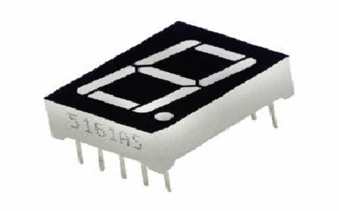
seven Segment Display
These displays are too bachelor in a wide multifariousness of styles from 0.3″ displays up to iii″ or larger displays.
7 Segment Display Pinout
The seven-segment display includes 10 pins where each pin is explained below.
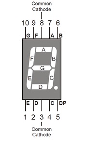
vii Segment Display Pinout
- Pin1 (east): This pin is used to control the left bottom LED of the display
- Pin2 (d): This pin is used to control the bottom-most LED of the display
- Pin3 (Com): This pin is used to connect to Vcc or Ground-based on brandish blazon
- Pin4 (c): This pin controls the right bottom LED of the brandish
- Pin5 (DP): This pin controls the decimal point LED of the display
- Pin6 (b): This pin controls the top right LED of the display
- Pin7 (a): This pivot is used to control the topmost LED of the brandish
- Pin8 (Com): This pin is connected to Vcc/GND based on display type
- Pin9 (f): This pin controls the top left LED of the brandish
- Pin10 (k): This pivot is used to control the heart LED of the display
Types of vii Segment Display
7 Segment Displays which have seven LEDs are arranged in a mode that can brandish numbers from 0-9. 7-segment displays are continued to the microcontroller in the aforementioned style equally LEDs (i.e. in series with a current limiting resistor). The only difference is that they have 8 pins rather than ii pins because each of the 7 LEDs has its own pin along with a mutual cathode or anode pin. There are two main types of seven-segment displays:
Please refer to this link for 7-segment Display MCQs
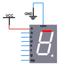
7 Segment Display Common Anode:
In this type, all LEDs share a common anode terminal while each cathode terminal is connected to a unlike segment. In club for a segment to light upwards, the corresponding cathode terminal will be grounded and the common anode last is provided with +5V source voltage. To interface a common anode type to a microcontroller and then the Cathodes of each segment are continued through appropriate port pins of the microcontroller. When we want to plough on any particular segment so we demand to utilize logic nil on the respective cathode.
Common Anode vii Segment Brandish
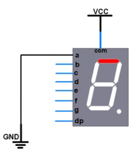
seven Segment Display Common Cathode:
In this type, all LEDs share a mutual cathode terminal while each anode terminal is connected to a different segment. In club for a segment to calorie-free up, the respective anode terminal will exist provided with +5V source voltage and the common cathode terminal will be grounded. To interface a common anode blazon to a microcontroller so the Anodes of each segment are connected through appropriate port pins of the microcontroller. When nosotros want to turn on whatsoever particular segment then we need to apply logic loftier on the respective anode.
Common Cathode 7 Segment Display
Other forms of vii-segment display include: A pop variant of the 7 segments LED display is the iv digits 7 segments LED display. As evident from the name itself, a four digit vii segments LED display consists of iv seven segment LED displays connected together in such a manner that they can display any number between 0000 to 9999 with the aid of a counter IC similar the CD4033, or a LED driver MAX7219.
The fourteen-segment display has iv boosted diagonal bars between the top horizontal and middle vertical segments; it was used on some early pocket calculators.
The xvi-segment display adds four diagonal confined between each set of two adjacent vertical segments; it is used on some calculators and watches.
seven-segment Display Working
The truth tabular array of vii segment brandish is shown beneath which includes decimal digits from 0 to 9 and individual segments illuminated from a to 1000.
| Decimal Digits | a | b | c | d | e | f | g |
| 0 | 0 | 0 | 0 | 0 | 0 | 0 | 0 |
| ane | 0 | 1 | `1 | 0 | 0 | 0 | 0 |
| two | i | 0 | 0 | 1 | 1 | 0 | 1 |
| 3 | one | 1 | 1 | 1 | 0 | 0 | 1 |
| four | 0 | ane | 1 | 0 | one | i | 1 |
| 5 | 1 | 0 | ane | 1 | 0 | one | i |
| 6 | i | 0 | ane | 1 | i | 1 | 1 |
| seven | 1 | 1 | one | 0 | 0 | 0 | 0 |
| 8 | 1 | 1 | i | one | 1 | i | 1 |
| ix | ane | 1 | i | 1 | 0 | 1 | 1 |
The working of the 7-segment display can be done by glowing the necessary individual LEDs within the digit. The display can be controlled through freely left pins. Once these pins are forward biased in a series then it volition display the specific alphabet or numeral. Based on the seven-segment type, the segment pins are practical with logic zero or high & in the same method to the common pins too.
Once the power of a seven-segment brandish is ON so an 8 number will be displayed. If we disconnect the power, particularly for 'k' so it will brandish equally '0'. For instance, if you want to display numeral 'ane' and so both the segments similar b & c need to be switched ON & the remaining segments volition be switched off.
seven-segment Display Interfacing with Arduino
The circuit of a 7-seg brandish can be easily implemented past connecting 8 LEDs in a specific pattern as shown in the below figure. You must have noticed that each segment (a, b, c, d, e, f, g) is assigned a letter from A to G. This is done to correctly place the pattern of connections between them and the input pins of the microcontroller.
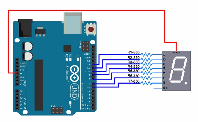
seven Segment Display Interfacing with Arduino
Interfacing a seven-segment display with Arduino is shown above. In this excursion, a common anode seven segment display is interfaced to the Arduino UNO board to display 0 to ix digits within a loop. So the interfacing diagram, required components, code, and its working are discussed below.
The required components of this circuit mainly include Arduino UNO, breadboard, power supply, seven-segment brandish, seven 220Ω resistors, and connecting wires.
The connections made from 7 segment display pins to Arduino board pins follow as;
- From Pin-a of seven segment display to pin13 of Arduino board.
- From Pivot-b of 7 segment brandish to pin12 of Arduino lath.
- From Pin-c of 7 segment display to pin11 of Arduino board.
- From Pin-d of seven segment display to pin10 of Arduino board.
- From Pin-due east of vii segment display to pin9 of Arduino lath.
- From Pivot-f of vii segment display to pin8 of Arduino board.
- From Pivot-one thousand of seven segment display to pin7 of Arduino board.
In this excursion, a common cathode type seven Segment Display is used. And so the common pin can be merely continued to Arduino board Pin 9 & is fabricated HIGH always.
In mutual cathode blazon, reverse the logic from LOW with HIGH & High with Low. Because in this blazon, LED lits once some +positive voltage is provided to any pin.
Project Code
//Seven segment brandish with arduino uno
void setup() {
int a = 13; //Arduino pins connected with seven segment pins
int b = 12;
int c = 11;
int d = x;
int e = nine;
int f = viii;
int chiliad = seven;
void setup() {
//Declaring all the pins equally output
pinMode(a, OUTPUT); pinMode(b, OUTPUT); pinMode(c, OUTPUT);
pinMode(d, OUTPUT); pinMode(due east, OUTPUT); pinMode(f, OUTPUT);
pinMode(g, OUTPUT);
}
// the loop routine runs over and over again forever:
void loop() {
digitalWrite(a, Loftier);
digitalWrite(b, High);
digitalWrite(c, HIGH);
digitalWrite(d, High); //Generating 1
digitalWrite(e, Low);
digitalWrite(f, Low);
digitalWrite(thousand, High);
delay(thou); // look for a second
digitalWrite(a, LOW);
digitalWrite(b, LOW);
digitalWrite(c, High); //Generating 2
digitalWrite(d, LOW);
digitalWrite(e, Depression);
digitalWrite(f, HIGH);
digitalWrite(g, Depression);
delay(1000); // wait for a 2d
digitalWrite(a, Depression);
digitalWrite(b, LOW);
digitalWrite(c, LOW);
digitalWrite(d, Depression); //Generating 3
digitalWrite(e, HIGH);
digitalWrite(f, Loftier);
digitalWrite(g, Low);
delay(chiliad); // wait for a second
digitalWrite(a, High);
digitalWrite(b, Depression);
digitalWrite(c, Low);
digitalWrite(d, High);
digitalWrite(east, Loftier); //Generating four
digitalWrite(f, Low);
digitalWrite(g, Low);
delay(thousand); // look for a second
digitalWrite(a, Depression);
digitalWrite(b, Loftier);
digitalWrite(c, LOW);
digitalWrite(d, Low);
digitalWrite(e, HIGH); //Generating 5
digitalWrite(f, Depression);
digitalWrite(g, LOW);
delay(g); // await for a 2nd
digitalWrite(a, LOW);
digitalWrite(b, HIGH);
digitalWrite(c, LOW);
digitalWrite(d, LOW); //Generating 6
digitalWrite(e, LOW);
digitalWrite(f, LOW);
digitalWrite(g, Low);
delay(one thousand); // wait for a second
digitalWrite(a, LOW);
digitalWrite(b, LOW);
digitalWrite(c, Low);
digitalWrite(d, Loftier);
digitalWrite(e, High); //Generating vii
digitalWrite(f, Loftier);
digitalWrite(m, HIGH);
delay(thousand); // wait for a 2nd
digitalWrite(a, Depression );
digitalWrite(b, LOW);
digitalWrite(c, Depression);
digitalWrite(d, LOW);
digitalWrite(e, LOW); //Generating 8
digitalWrite(f, LOW);
digitalWrite(g, LOW);
delay(g); // wait for a second
digitalWrite(a, LOW);
digitalWrite(b, LOW);
digitalWrite(c, LOW);
digitalWrite(d, HIGH);
digitalWrite(e, HIGH); //Generating ix
digitalWrite(f, LOW);
digitalWrite(g, Low);
delay(1000); // look for a second
}
In order to activate a specific segment, for case, segment 'a', the equivalent Arduino Pin should be made Loftier. So, here the segment 'a' is simply continued to pin-13 of the Arduino board. In the aforementioned style, other segments tin can too be made Loftier. Based on the to a higher place truth table of the 7-segment display, depending on the selected segments, a digit can be simply displayed on the vii Segment Display.
seven-segment display Advantages
7-segment displays have some advantages they are
- Inexpensive and extremely popular and simple structured.
- Since the digits share common cathodes or anodes, they tin be driven by a single commuter IC (although usually two separate driver ICs are used – one for the cathodes and ane for the anodes). The driver ICs can sink or source electric current from a microcontroller output pivot, which makes them like shooting fish in a barrel to interface to microcontrollers in digital systems.
- A large number of LEDs in each digit means that they tin be easily read at a distance or in low calorie-free.
- But four point lines are required to control each digit (ane signal line for each segment, plus one bespeak line to select the digit). This makes them easier to implement.
- Information technology consumes piffling power, making it appropriate for bombardment-driven devices such as calculators.
- It is easy to distinguish between numerals and other alphabets or symbols.
7-segment Display Disadvantages
The disadvantages of the seven-segment brandish are;
- Information technology can brandish simply numerals, HEX values, and some predefined characters. It cannot display other symbols like alphabets, other than the English language characters.
- It has low resolution.
- It is not suitable for the brandish of decimal points. For the decimal point, a separate extra LED is required.
Applications
The applications of the 7-segment display include the following.
- 7 segment displays are mostly used in electronic meters, digital calculators, clock radios, digital clocks, digital clocks, odometers, etc.
- At present, most of the seven-segment display applications are with LCDs due to low power consumption.
Thus, this is all about an overview of a 7 segment brandish and information technology's working with applications. The interfacing of a seven-segment display with an Arduino is used to display 0 to ix digits with ease. So these display devices are mainly applicable in bigger electronics projects like Warning Clocks, object counters, timer circuits, digital clocks, etc. Here is a question for you, what are other dissimilar displays used in electronic projects?

7 Segment Display Karnaugh Map,
Source: https://www.watelectronics.com/7-segment-display/
Posted by: witherswhook1942.blogspot.com
0 Response to "7 Segment Display Karnaugh Map"
Post a Comment